The Canon USB-Video Splitter - IT WORKS!
I wasn't the first person to build one of these splitters(*1), but after using CHDK (the Canon Hack Development Kit), and ptpcamgui (a cool piece of software written by some intuitive individuals), I thought that I really should be able to use ptpcamgui for some really cool stuff.
The problem is/was that when I connected the USB cable to my camera, the LCD screen blanked out.(*2)
This made it hard to tell what the camera was doing. This has since been fixed, so seeing the camera while it is right in front of me is not a problem. But when I actually put this all into practice, the camera will be 30 feet away from me (up in a tree). I won't be able to see the LCD from that distance, so I'll need a video transmitter and I'll need to connect that video transmitter to my USB!
So there was the trouble. I needed the USB to control the camera, but I also needed it to view the video output. I have a Canon SX130is, and I know this also be required for the SX30 and any others that use the "AVC-DC400ST" video cable plugged into the USB port to view video.
No matter how I tried, I couldn't find something that did what I needed. I tried to find any type of cable that used a standard Mini USB plug and had 11 pins, but I really don't think that one exists(*3).The next best thing is called an "Enhanced Mini USB" or EMU. The problem is that the EMU plug is shaped differently. It is slightly larger, and mainly square with one corner "notched".
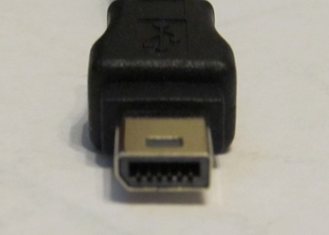
Figure 1 - Example of an Enhanced Mini USB Plug
These connectors seem to have been engineered by HTC or another cell phone company for the main purpose of using a headset while charging your cell phone. Knowing that this connector has all of the pins I need, and knowing that someone else had made this not-quite standard connector work with a standard Mini USB female connector, I started searching for devices/cables that had this type of connector attached. I found the HTC USB Splitter (these cost $2.99). I have since found others(*3), but this is still the cheapest and coolest
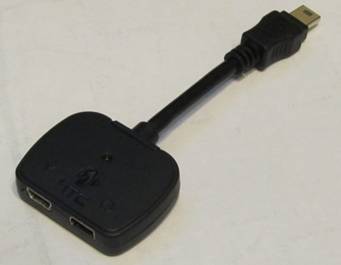
Figure 2 - The HTC USB Splitter
The first thing to do is to take the metal cover off of the plug.
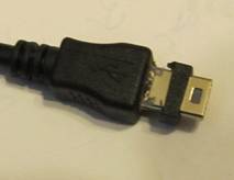
Figure 3a - Carefully cut plastic from sleeve
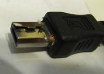
Figure 3b - Carefully pry metal sleeve to remove
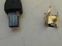
Figure 3c - Metal sleeve removed
With this USB splitter, it was pretty easy to CAREFULLY cut away the plastic from around the metal sleeve and then using a screwdriver pry the metal sleeve away from the plastic core (again, be careful!). I did this with a few of these splitters, and with the first one I just pulled the sleeve until the ground wire broke. I wouldn't really recommend this, because I don't know how it's wired farther into the plug, and you may disconnect the other ground. I would recommend using a file to cut the sides of the metal sleeve, or bending that side (the straight side) back and forth until it just breaks off.
Once that is done, it is very easy to cut or file the flat side so that it has an angle just like the other (cut-out) side.
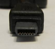
Figure 4a - Connector filed to fit
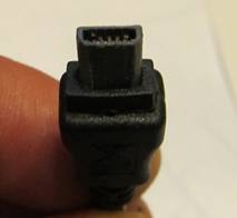
Figure 4b - Freshly trimmed connector
Without forcing it into your camera, test fit your new plug (Camera turned off, nothing plugged in to your USB splitter). You want it to fit, but not too tightly. If it doesn't fit, trim it down a little more. I didn't feel comfortable cutting the plug down enough to fit a regular Mini USB metal shield/sleeve on it, but it fits into the camera perfectly without, so I didn't worry too much. If you cut the rubber sleeve off carefully and didn't destroy that little piece you took off, you can slip it back on to the connector so it looks "prettier".
That was the easy part.. BUT you're not done yet!
Although some of the pins look like they would be standard USB (the pins on the charger side), they are not.
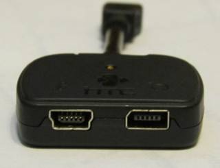
Figure 5 - Non Standard Mini USB on left, Enhanced Mini USB on right
For our Camera, we are looking for the following pinout:
Pin 1 - 5V
Pin 2 - Data -
Pin 3 - Data +
Pin 4 - N/C
Pin 5 - Ground
The HTC Splitter is close, but not quite there It uses this pinout:
Pin 1 - 5V
Pin 2 - Data -
Pin 3 - Data +
Pin 4 - Device Identifier
Pin 5 - Shield Ground for EMU socket (?)
Even though the plug now fits into your camera, and you can plug a standard USB mini cable into one side of the splitter (AND the light on the splitter lights up), it just won't work. Why? Because Pin 5 isn't really ground - it's whatever HTC wanted to use it for, AND Pin 4 is connected as a device ID.
Carefully cut/pry apart the two halves of the splitter housing. If you are careful prying it apart, it fits together again very nicely.
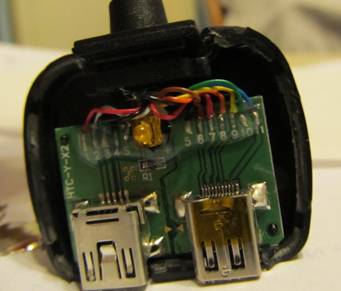
Figure 6 - USB Splitter housing pried apart
What next? Cut the wire going to pin 4. You just don't need it there. Tuck it behind the rest of the wires so it doesn't confuse you during the next step.
Now on the other side of the LED (the side with yellow, orange and blue wires.. let's call it the right side), you can cut ALL of the wires off of the board (as close as you can to the board so you have room to work.) Keep track of the BLACK wire that was connected to pin 5 on this side, you need it. DON'T confuse it with the other black wire you cut from pin 4, it's not the same.
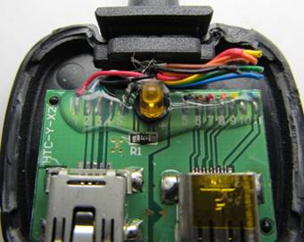
Figure 7 - Cut all wires from pins 5-11 on the right side
Carefully strip the end from the Black wire that was connected to pin 5 (previous step), and wrap/solder it to the braided shield (on pin S from the OTHER side). This is just the easiest way to do it with big fingers like mine!)
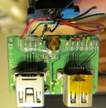
Figure 8 - Black wire from right soldered to board/braid on left
At this point, you have 3 inch USB extender with an indicator light. It works with your Canon camera and you can connect to the PC for picture transfer, or to use PTPCamGui (Yay!) BUT, you also have some wires left over - 7 to be exact, and you won't even need all of them!
This USB Splitter also has an EMU port for the headset it was designed to be used with. We can't use that at all - standard mini USB plugs don't fit and the wiring is wrong for us anyway. Carefully pry it off of the circuit board< (easier said than done, but a soldering iron helps).
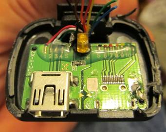
Figure 9 - EMU socket removed to make space for wire
Now we're almost ready to connect our Audio/Video Cable. Here are the colors on the splitter and where they go:
Red - pin 11
Purple - pin 10
Orange - pin 9
Yellow - pin 8
Green - pin 7
Blue - Pin 6
Black ? (maybe shield ground.. I had removed the shield before testing and couldn't find a connection)
Here are the pinouts for the Canon AVC-DC400ST Video/Audio cable, and the colors on the splitter to connect them to.
11 - GRND - (vid/aud -) - (Red wire on our connector.)
10 - Composite Video + (Purple wire on our connector.)
9 - Left (white) Audio + (Orange wire on our connector.)
8 - Right (red) Audio + (Yellow wire on our connector.)
7 - N/C -
6 - GRND (vid/aud -) Video out enable. (If connected to blue wire on our connector, video is output via cable. May put switch to change between LCD and video output)
On the standard Canon audio/video cable, pins 6 and 11 (red and blue) seem to be tied together. This causes the camera to start outputting video and audio any time the cable is plugged in. You can put a switch between pin 6 (blue wire) and ground and be able to switch from video output via cable to LCD display without unplugging the cable. (this has only been tested on a Canon SX130IS)
If you do not want to switch between the LCD and cable output, just tie all of the RCA cable grounds together, and solder them to the blue and red wires (video enable is always on).
Then solder the corresponding RCA cable wires to the correct color wires on the splitter (RCA video to splitter purple, RCA left audio to splitter orange, RCA Right audio to splitter yellow). I just cut off the extra green and black wires.
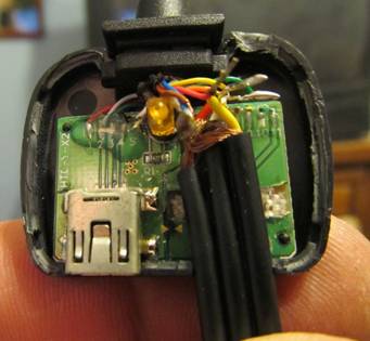
Figure 10 - Video/Audio cable soldered to the correct wires
Make sure you insulate all of the wires from each other and the circuit board (tape, shrink tube, whatever works for you). If you want, you can use hot glue to seal everything inside and keep the solder joints from getting tugged by the wire.
If you cut/pried the two halves of the splitter apart carefully enough, you might be able to snap it back together. If not, just use glue or tape. (I used glue).
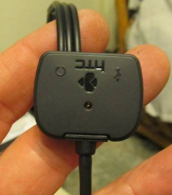
Figure 11 - Case snapped back together
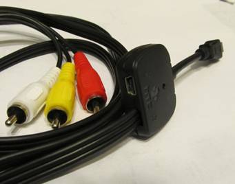
Figure 12 - The finished product
Now if you soldered carefully, and got all of the wires in the right places, you should have a fully functional Canon CHDK USB/Video Splitter cable! If you use a USB remote plugged into it, the light on your splitter will light up while you press the button. It's very handy to know that your batteries are good and that you actually pressed the button on your remote switch!
*1 -Need link to other usb-video splitters
*2 - I have discovered that the WIA service connection to the camera causes the screen blank. If you disable WIA service, the screen doesn't blank when connecting with ptpcamgui. **NEEDS VERIFICATION.
*3 - Found a standard USB cable and connector that utilizes all pins - see camremote cables **NEED LINK